


In most buildings the ceiling closes a room off. In a semiconductor cleanroom it does the opposite: it is the surface through which clean, conditioned air enters, and it sets the airflow pattern that keeps sub-micron particles away from the wafer. Get the ceiling wrong and no amount of gowning, filtration capacity or floor cleaning will recover an ISO Class 5 environment.
This article looks at the ceiling as an engineered air-delivery system for advanced electronics manufacturing: why unidirectional (laminar) flow is non-negotiable at ISO 5, how the filter-and-grid plane is built to deliver it, how the return path through a raised floor closes the loop, and the contamination and static issues that are specific to the ceiling itself.

01 — The core requirement
Why ISO Class 5 forces a unidirectional ceiling
Cleanliness classes from ISO 14644-1 cap the number of airborne particles allowed per cubic metre. At ISO Class 5 the limit is 3,520 particles ≥0.5 µm per cubic metre — roughly a thousand times cleaner than a well-run office. A single fingerprint-sized burst of contamination near a lithography or etch step can scrap a wafer, so the air at the work plane has to be continuously replaced before particles can settle.
Turbulent, mixed-flow ventilation — the scheme used in lower-grade rooms and in most of a typical modular cleanroom — dilutes contamination but cannot guarantee it is swept away from a specific point. ISO Class 5 and cleaner processes therefore rely on vertical unidirectional flow: a uniform sheet of filtered air moving top-to-bottom across the whole room at a steady velocity, typically 0.30–0.50 m/s. To produce that sheet, the ceiling cannot be a few scattered diffusers; it has to become an almost continuous filter plane.
This is the first design consequence that separates a fab cleanroom from a general one: the ceiling, the filtration and the floor return are a single aerodynamic system, and the ceiling is where it starts.
02 — The filter plane
Filter coverage, velocity and the FFU ceiling
The degree to which the ceiling is filled with filters — the filter coverage ratio — is what physically determines whether flow stays unidirectional. Higher classes demand more coverage:
| ISO 14644-1 class | GMP equivalent | Airflow regime | Typical ceiling filter coverage |
|---|---|---|---|
| ISO 5 | Grade A / B | Unidirectional | 60–100% |
| ISO 6 | Grade C | Uni- or non-unidirectional | 20–40% |
| ISO 7 | Grade C | Non-unidirectional | 10–25% |
| ISO 8 | Grade D | Non-unidirectional | 5–15% |
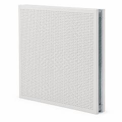
For most semiconductor cleanrooms this coverage is delivered by an array of Fan Filter Units (FFUs) dropped into a modular ceiling grid. Each FFU contains its own EC fan and a HEPA or ULPA filter (ULPA U15 reaches 99.9995% at the most penetrating particle size), so airflow can be tuned cell by cell rather than balanced from a distant air handler. Where a process is exceptionally sensitive, designers push coverage toward 100% so that the entire work area sits under moving filtered air.

Because every FFU is an active component that will eventually be serviced, the grid that carries them is as important as the filters — which is the next problem to solve.
03 — The grid
The ceiling grid: load, sealing and access
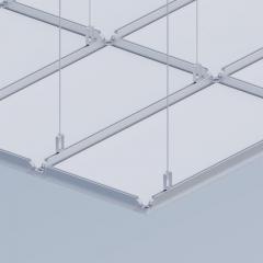
The suspended grid — usually an extruded aluminium T-bar ceiling system — has to do three jobs at once. It must carry weight, seal against air bypass, and allow filters to be changed without contaminating the room below.
Load. A populated ceiling is heavy: FFUs, lighting, sprinklers, sensors and process services all hang from it, and in a fab the grid may also need to be walkable so technicians can service units from above without entering the clean space. A 55 mm-class structural grid on a regular module, suspended on M10 threaded rods with levelling adjusters, spreads these loads while keeping the underside flush.
Sealing. Any gap between a filter and the grid is a leak that breaks unidirectional flow. Quality grids use a continuous gasket or gel-channel seal so each FFU and blank panel sits airtight, and the framing is designed without dust-collecting ledges on the room side.


Access. A standardised module matters here too: when filters reach the end of their life, a service team should be able to lift a unit from the walkable deck, drop in a replacement and re-seal it in minutes. Designing the FFU ceiling grid system and the building’s service plenum together is what makes that possible.
04 — Closing the loop
The return path and pressure balance
Air pushed down from the ceiling has to leave cleanly, or it recirculates and re-deposits particles. In a true unidirectional room the return is not a few wall grilles but the entire floor: an anti-static perforated raised access floor through which air is drawn back to the fan plenum, re-conditioned and returned to the FFUs. This top-supply, bottom-return loop is exactly what was used on precision-electronics projects such as the Kunshan electronics fit-out, pairing the filter ceiling with raised perforated flooring.
Schematic — not to scale. Real fabs add make-up air, AMC filtration and tool exhaust to this loop.
Pressure cascade. The cleanroom is held at positive pressure relative to its surroundings so that any leakage flows outward, never in. Typical steps are around 10–15 Pa between adjacent zones, maintained through airlocks and tightly sealed enclosures. The ceiling contributes by being leak-tight: an unsealed grid bleeds the pressure the whole strategy depends on.
05 — Ceiling-specific risks
Particles, outgassing and static at the ceiling
Because the ceiling is upstream of everything, its own materials matter more than anywhere else in the room. Three risks are specific to it:
- Particle shedding. Bare or poorly finished metal sheds fibres and oxide. Ceiling components should be powder-coated or anodised, burr-free and free of horizontal ledges where dust can accumulate.
- Outgassing and AMC. Semiconductor processes are sensitive to airborne molecular contamination — trace acids, bases and organics that no particle filter removes. Sealants and gaskets must be low-outgassing, and critical zones add chemical (gas-phase) filtration into the ceiling plenum.
- Static. A charged surface attracts particles and can damage devices through electrostatic discharge. Ceiling grids, panels and the raised floor should be electrically bonded and grounded so the whole envelope dissipates charge.
These are the same surface principles that govern cleanroom wall panels — smooth, sealed, non-shedding, cleanable — applied to the most critical plane in the room.
06 — Building it
Why ceilings are designed and prefabricated as a system
Everything above interlocks: coverage sets velocity, velocity sets the return area, the return sets floor design, and grid sealing protects the pressure cascade. Tuning these on site, one trade at a time, is slow and error-prone. This is why high-grade ceilings are increasingly engineered as a coordinated, prefabricated assembly — grid, FFUs, lighting, blanks and service penetrations dimensioned to one module and tested before they reach the floor.
The modular approach also protects the future. A standardised grid can be re-populated as a process node changes — more FFUs added, a bay reconfigured, a room relocated — without rebuilding the shell. For a fab whose tooling evolves every few years, a ceiling that can be re-tuned is as valuable as one that is clean on day one.
Key takeaways
- ISO Class 5 requires vertical unidirectional flow, which only a near-continuous filter ceiling can deliver.
- Filter coverage (often 60–100% for ISO 5) and a steady 0.30–0.50 m/s face velocity define performance.
- The grid must carry load, seal against bypass and allow walkable filter service.
- A perforated raised-floor return and a positive pressure cascade close the loop.
- Ceiling materials must be low-shedding, low-outgassing and grounded to control particles, AMC and static.
Planning a high-classification ceiling?
Wonclean designs and prefabricates FFU ceiling grids, filter plenums and the matching wall and floor interfaces for ISO Class 5 semiconductor and precision-electronics cleanrooms. Share your class, layout and tool loads and our engineers will model the coverage and airflow for you.
FAQ


 온라인 서비스

